Electronic Ignition
Capacitive Discharge Ignition ( CDI )
Transistor Controlled Ignition ( TCI )
This guide explains the basic principals and theory behind electronic
ignition.
This is linked from the (Yamaha Vision
Motorcycle Ignition FAQ) & my (Vision
Home Page).
If you have inputs to this page .... PLEASE email
Dave "Leather" Draper JetAv8r@JetAV8r.com
![]()
Last Update June 20005. Download
This Guide As PDF (Zipped File)
Intro This guide was started for a motorcycle group seeking to solve common ignition problems. But over time, this has expanded into this stand-alone page because of the interest for a general explanation of gas 4-stroke (not diesel or 2-stroke) engine ignition principals. Everyone at one time or another has suffered through some ordeal caused by a non-working ignition system. Whether its the lawn mower, outboard, chainsaw, or the time you drove your Dad's car through that big puddle..... you've been stuck somewhere or with something that would not run. When troubleshooting non-running engine problems I've always used the "GAS" method : "gas, air, spark". Have those 3... something should happen. So this is a discussion of how we get the Spark part.
Review of basic ignition designs
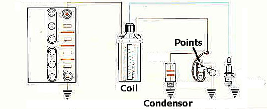
Basic Points/Distributor/ Coil.
("Kettering" design)
A Frenchman named Etienne Lenoir invented the electronic spark plug in 1860. Spark plugs haven't really changed THAT much since then. But "firing" that spark plug has been a better evolution. The Father of ignition is Charles Franklin Kettering (man pictured left). In 1909, Kettering, in association with Edward A. Deeds, organized the Dayton Engineering Laboratories Company (Delco). As you've already started to guessed from the name... they invented the first automobile generator. That road to the generator invention brought them all the design concepts that would be used to dream up starter motors, ignition system components, etc.. So, it is in 1910 that Kettering began work on new automobiles electrical systems. Also notably, he invented the first "self-starter" in 1912. Within two years, most cars were equipped with this new device. Kettering went on to become head of General Motors research laboratories and Vice President of the Corporation. "Boss Ket" would eventually receive over 160 U.S. patents for his ideas.
It is in 1911 that he developed the first electrical ignition system (or at least the design concepts that lead to that invention). These early patents are hard to trace, but a little research shows Kettering invented the "engine, starting, lighting, and ignition system" (Patent 1171055 featured here in PDF). This early type of ignition design is known as the Kettering system (points/condenser/coil) or "induction" system. It became the standard in the automotive industry replacing magnetos. It is rugged and reliable but has drawbacks as you will see. A "lighting coil", "lighting" system is a more tradition term for an auto/motorcycle type self powered generator system. So you and I know Kettering more as the man who invented the first practical engine-driven generator (known as the "DELCO" generator). This was Patent No 1150523.
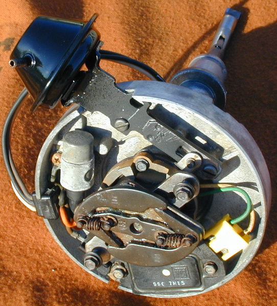
A basic Kettering Ignition Design A chain, belt, or gear from the engine drives a "DISTRIBUTOR". Inside this distributor is a spring loaded contact switch ("POINTS") riding on a revolving cam. The points would open and close to fire a single coil which would produce the spark for the spark plugs. Inside the distributor is also a "ROTOR" which rotates to determine which plug wire gets the spark.
A.To Coil
B. Points
C.Points Dwell Adjustment
D. Point Riding On Cam
E. Rotating Cam Driven
.....by engine
F. Condensor
Magnetism and Induced Current
In the mid 1800's Michael Faraday (and others ... though "micro Farads " to this day is the measurement of capacitance) developed the concept that a current passing thru a coil wire creates a magnetic field. More importantly, a magnet passing by a coil wire creates a voltage current. The amount of current depends on the magnetic size and speed (rate) the magnetic field passes (or changes) by the coil. The math equation for this is e=-df/dt. The change in magnetic field strength is df and the time (rate of change) is dt. Technically, e is the "Induced EMF". But we talk of this as the current produced in the wire coil ... actually a PULSE.
Automotive COIL (also called an "INDUCTOR")
An iron core is wrapped with 2 long "coils" of wire. The "PRIMARY" winding on the outside and the longer "SECONDARY" winding on the inside. The wire length ratio is typically 100:1 (the secondary is 100 times longer than the primary).
The coil is fed 12v to the primary winding. This in turn creates a large (enhanced by the iron rod) magnetic field which also surrounds the Secondary windings. The coil is now storing a large magnetic field (a Flux" field). When the +12v to the coil primary winding is turned off the magnetic ("flux") field inside the coil "collapses". This causes a "Back EMF" (Electro Motive Force) current in the primary wire of about 200-300volts. THIS IS IMPORTANT. Most think the coil converts 12v to 30,000 volts. Not exactly. See, this back EMF voltage of 300volts is now applied to both windings. When the coil collapses this rapidly changing magnetic field is also transferred to the "Secondary" windings as current (remember the discussion above about magnetism... "a changing magnetic field passing by a coil creates electric current").
The Secondary winding is 100 times longer so produces a voltage about 100 times more than the Primary during collapse. Lets do the math. The Primary ("Low Tension") wire is about 300v during the Back EMF spike. So the Secondary ("High Tension") wire is 100 x 300=30,000 volts. This high voltage is going somewhere, somehow to ground. The faster the power cutoff is in the primary, the faster the collapse, and the faster (more powerful) that spark is. So, when the points open (instantly cutting off power to the coil) 30,000 volts goes to ground from the secondary winding via the spark plug.
If you've understood some of this then you should be asking: "how does the primary winding collapse to ground if the points just opened its connection with ground?!??" BINGO! To get the primary winding to collapse in the proper fashion, we got to give it a way to get back to ground during the collapse!
INTRODUCING THE "CONDENSER"
Ok, quick review: Due to magnetic "flux" properties (research Teslar and the "left hand rule" if you want to know more) the inductor (COIL) encourages current flow towards the plug from the secondary winding. But the collapsing magnetic field also produces the phenomenon discussed above called "Back EMF". This 300+ voltage spike in the primary winding would cause a mini-spark of it own across the points. Another words, the primary winding would cause a spark across the points just like the secondary will cause a spark across the plugs. To facilitate the collapse of the primary winding and to prevent point-gap spark a condenser is used.
The condenser is a large capacitor. Only the automotive industry calls it a condenser (and no, I have no idea why). When the points open this coil collapses. Remember, a coil output is strongest when the collapse is fast and sharp. The condenser slows this collapse by absorbing the initial shock (current) of the primary winding. It helps shape the coil collapse to produce the high power secondary collapse AND slows the collapse of the coil just long enough for the points to get far enough apart so the coil back EMF output won't arc across the points. Without a condenser the backflow arcing and heat would destroy the points (sometimes in a matter of seconds). However, the condenser can't be too big either or the coil would collapse too slow and not produce a strong spark. The charge the condenser absorbs while the points are open is releases back to ground when the points close again.
The capacitor also "harmonicly" tunes the coil, raising the peak output voltage and increasing the secondary voltage rise time. This increases the amount of energy transferred to the spark plugs. If the coil secondary voltage rises too quickly, excessive high frequency energy is produced. This energy is then lost into the air-waves by electro-magnetic radiation from the ignition wiring instead of going to the spark plugs where we would like it to go.
Coil output is a function of coil windings "turns ratio" and also voltage input. The more power you put in the more you get out, right? And more power is better, right? Well..... no. We'll talk more about higher coil outputs later, because it becomes a bigger issue with CDI where you can REALLY pump out some voltage. It only takes about 10-15,000 volts to start the spark. Higher voltage is better because it can jump a larger plug gap (which is good for igniting the charge) and for overcoming ignition wear (worn/fouled plugs, wires, etc...). A longer duration is also preferred because the EXACT millisecond the fuel charge will ignite is shifting slightly. But big problems occur with high coil outputs also. "Flashover" refers to the discharge of the ignition voltage anywhere other than at the spark plug gap. Too high a voltage and frequency and the ignition is going to arc wires, leak out the side of the coil, plugs, or convert to EMF.
The goal is to get a good strong spark with good duration and one that jumps a good spark gap. Points are a mechanical switch limited by how much current you can pump through them without burning them up. So, in the ignitions points limit the amount of power you can put into the coil. Points are limited to about 250volts and 5 amps. Coils can handle up to about 7 amps and transistor switches about 10-20 amps. By the way, the math for coil output is: e=L*( di/dt), which is..... voltage = (coil inductance) times (the rate of change of primary current as the stored coil current discharges).
MORE COMPLICATED COIL FOOD FOR THOUGHT It gets more con"DENSER" than you thought. To really get technical, a coil is really just an iron core transformer (a step up transformer). This concept becomes more important when we talk about CDI. But for now, we'll talk about a transformer we've powered up with 12volt DC. That sounds reasonable except that a transformer only works with "AC" current. What? I'm so confused. Yeah, me too.
The points are opening and closing this electric flow thru the coil (back-forth) at this really high rate. Hmmmmm, that sounds a lot like "AC" current. See, the points have actually created this psuedo sort-of AC current. The whole system resonates at some frequency. That's why you hear car ignitions on the radio. The circuit resonates at some "tuned" frequency that any engine (at some RPM) can produce in the am/fm frequency band.
BALLAST RESISTOR In order to increase the coil voltage at startup some ignition designs incorporate a "ballast" resistor. The resistor is switched in and out of the supply voltage to the coil. Once running, the resistor is switched in place and the coil is actually getting less than 12volts. When the engine is started, the resistor is removed and the coil gets the full 12volts. This provides a much better spark at startup to compensate for reduced battery voltage drawn by the starter. When starting a cold engine, the plugs and the air are cold, the cylinder pressure is up, and the fuel / air mixture is poorly controlled. The oil is thick, the battery is cold and its voltage drops as much as 60% because of the high current drained by the starter motor.
DWELL Conventional ignition is affected by "Dwell time" (or dwell angle). Dwell time refers to the time the points are closed thus recharging the coil. Dwell angle refers to the crankshaft angle of rotation made while the points are still closed. As an example, if we talk about a 2 cylinder engine then the available dwell angle would be 180 (360 degrees divided by 2=180 degrees). If dwell time or dwell angle (points closed) is too short the coil may not have enough time to charge at high RPM. So large dwell is better right? But, if dwell is too large (points hardly open) then the points may not be open long enough for the coil to collapse at high RPM. The ratio of closed points to open is usually about 3:1.
The "dwell" time (points closed) has to be long enough for the coil to fully "charge". Typical dwell times (charge time) for a Kettering designed ignition are 1.0 to 6.0 milliseconds. Obviously, dwell time limits the ability of points to control a coil to deliver high power at high RPM. At high RPM you simple run out of time (you simply don't have 6 milliseconds). In addition, points are inherently a sloppy mechanical device to begin with. And worse, at high rpm they start to "float" off the cam. You can't get the points to "spring back" fast enough so instead of opening and closing they would hover just off the cam. Points can also have a phenomenon called "bounce", where they don't ride evenly on the cam. The upshot is that you can't control the coils fast enough at high RPMs. Some race teams got around this by using dual point systems overlapping the dwell times to get what they needed.
CHARGE TIME , VOLTAGE RISE TIME , SPARK DURATION Again, an induction coil setup charges (is "fully saturated") in typically 1-6 milliseconds. Race teams in higher RPM applications use low resistance coils to speed up the charge to about 3 milliseconds. (We'll see later it takes CDI about 1 millisecond). The time it takes for the coil to collapse and reach %90 of its peak potential voltage is referred to as voltage "rise time". The voltage rise time in conventional ignitions is about 100microseconds. The result is spark durations from inductive coil systems between 1-2 milliseconds.
As we'll see, CDI is a different animal. Here the voltage rise time is a short 6 microseconds, but the spark duration is shortened considerably also. The quick charge time is an advantage in high RPM settings but the short spark length is a disadvantage for starting and other high rpm compression/ratio fuel/mix situations. Because of this, the longer duration of inductive discharge systems is sometimes preferred over CDI.
Distributor with dual points
SPARK "TIMING" and COMBUSTION PROGRESSIONObviously, the timing of the spark is crucial to getting the full horsepower capability from an engine. So, we need to talk about the desired timing of the spark, why that changes, and how that gets changed while an engine is running. Most of us think when the spark plug fires, the gas/air mixture in the piston instantly explodes and that "exploding" pressure is what drives the piston down. Well.... sort of. Except, if the gas really did ignite all at once we really would have an "exploding" engine (pistons everywhere!). We have to slow down the process and take a millisecond by millisecond look at it.
In the perfect ignition process we would achieve efficient combustion progression at exactly the right time to produce the optimum pressure gradients in the cylinder in complete harmony with the piston movement relative to the piston rod to crankshaft rotation. Say W-H-A-T ??!!
The combustion process does not happen instantaneously-simultaneously in the cylinder but rather (as preferred) in a progressive pattern from the spark. The spark ignites gases near the electrode which then continues to burn (propagates outward) away from the spark plug usually a spherical pattern. You'll often hear this combustion progression across the cylinder referred to as the "flame front". The design of piston and cylinder heads, combined with spark plug placement is largely to get the best flame front possible. The time it takes the fuel/air mixture "charge" to combust changes according to many variables to include: fuel/air mixture ratio, density (temperature), octane, how well the cylinder has filled given volumetric efficiency, the "charge" turbulence inside the cylinder, compression ratio, the physical shape of the combustion chamber and piston head, spark plug placement, rear-end ratio and car weight (both translate to engine "load"), etc...
The important point here is:
The combustion process does take a period of time and the length of that time changes (so when you need to start it changes!).
An Example: Combustion Process Timeline with Before and After Top Dead Center Piston Position Timing at 3,000rpm 34Btdc 24Btdc 5Btdc 5Btdc - 15Atdc 10-20Atdc 20-25Atdc Spark
OccursCombustion pressure actually starts to overtake
normal cylinder pressure (without ignition).
This 10 degrees of lag is known as "Ignition-delay".
Normal cylinder pressure without ignition is called
the "compression line"Cylinder Pressure
near double normal
(compression line)Combustion
is now very
rapidPeak
cylinder
pressure
("PCP")Combustion
CompleteThe peak cylinder pressure occurs between 10 and 20 degrees "after piston top dead center" (ATDC) on most engines and the combustion process is complete by 20 to 25 degrees ATDC. The rise in cylinder pressure (pressure gradient) is technically called flagregation. Obviously we want the combustion process to occur during the down stroke and that high pressure point at the optimum point of leverage for the piston arm to crankshaft angle. To get this, the spark and combustion process must be started much earlier. Look at the graph above and you'll see at low rpm the spark occurs near 18 degrees before piston TDC (BTDC). From 5 degrees BTDC to roughly 15 degrees ATDC the combustion process is very rapid due to the progressing flame front and the high rate of energy release.
As RPM increases it becomes obvious that we must start the spark earlier or the combustion process will complete later in the "power stroke". Another words, we're not getting the best bang for our buck. Consider an example timeline. At 1,200rpm the crank is rotating 1 per every .05 second. Let's say the combustion process takes about 60degrees of that revolution so... about .008 second. At 6,000 the timeframe is 1/10 of that at .0008 sec. Typically, timing starts at a preset level (about 10-20 degrees) and then is advanced to be earlier as RPM increases. At about 3-4,000rpm the variables that change timing tend to even out and so no further advance is needed. In the example above timing advance caps at about 3,500 rpm to 38 BTDC. The graph above is known as the timing curve and while typical, can quite obviously be hugely different for other motors.
DETONATION ("engine knock", "ping", "pinging") While not advancing the timing would result in power loss, advancing the time to far ahead is even worse. If spark occurs too early then the combustion (and resulting PCP) can occur before TDC and the piston is still moving upward (not downward). This is BAD! Detonation in any form is destroying the piston head. I mean.... you can hear it banging itself to death!
PRE-IGNITION Pre-ignition is like detonation except it is less related to incorrect timing. Something else is causing the "charge" to ignite too early. Often, a lower octane gas could cause this because of its increased tendency to "auto ignite". Could be a hot spot in the piston head or hot carbon buildup on the spark plug end. Maybe the wrong "heat" rated spark plugs is being used for the type of engine use (plug running too hot). In any event, adjusting the timing can solve this phenomenon. Unfortunately, older motors were not adjusted for this while the motor was running, so the type of gas you used was locked in at the tune-up. Now, there's more lee-way as modern auto engines compensate for engine knock as part of the timing adjustments.
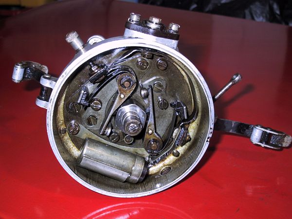
TIMING ADVANCE
Early Electronic Ignition Distributor with
dual points, centrifugal advance, and vacuum advance
In early ignitions the timing was advanced mechanically with RPM. Normally this done was with small weights and counter springs inside the distributor. As RPM increased, the weights were pull outwards by centrifugal force and shifted the points around the cam, changing the time they would open/close. The photo above shows the mechanical advance with spring. Can you notice also that the photo above is an early "electronic" ignition? So, ignition advance is necessary despite the "type" of ignition being used.
VACUUM ADVANCE We advance the timing trying get the perfectly optimum time for combustion during the power stroke. But as I mentioned earlier, there are many variables that effect how long the complete combustion process takes. So, advancing the timing based solely on RPM probably doesn't cover all the possible scenarios. But how do you tie those other variables into a mechanical contraption to adjust timing? You see the problem. To adjust the timing ever slightly more, autos in the 70's - mid 80's were fitted with an additional device called "Vacuum Advance".
A large factor in the rate of combustion is the density of the fuel/air mix (charge) in the cylinder. A low density mixture burns slower than a high density mixture. So, the spark needs to occur earlier when the fuel/mix charge is less dense which happens at closed (idle) or part open throttle (cruise = flat road) operation. At wide-open throttle (WOT) operation the fuel/air mix is dense and combustion is rapid, so no additional advance is needed.
This additional timing adjustment was made with a "vacuum advance". This is a clever device that ties manifold pressure to a mechanical advance mechanism. At "part-throttle" operation (like cruising on a flat road) the manifold vacuum is high and engine load is low. At full throttle (WOT) the manifold vacuum is low and engine load is high. Look at the above photo. The black device is the vacuum advance. The open port would normally be connected by hose to the intake manifold vacuum lines. A vacuum driven diaphragm on the distributor advances the spark even more when the manifold vacuum is higher. SO.... the spark is advanced more during closed or part throttle operation. Example:
Advance at Wide Open throttle = Initial Advance setting + Advance from centrifugal advance only
Advance at Close or Part-Throttle = Initial Advance setting + Centrifugal advance + Vacuum advanceTIMING ADVANCE SETTINGS/ADJUSTMENTS In earlier conventional ignitions you could adjust the initial timing by physically moving where the points were screwed onto the distributor. This would need to be periodically changed as the points wore down. They would also need to be changed as the engine got older and the cylinder compression was less due to ring/piston wear.
As for the timing advance: the centrifugal and vacuum advances were set by their physical mechanical design in the factory. No adjustments were normally possible. To change timing you could swap out the device with one from another car or another after market device.
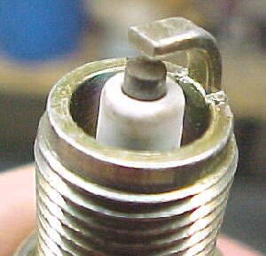
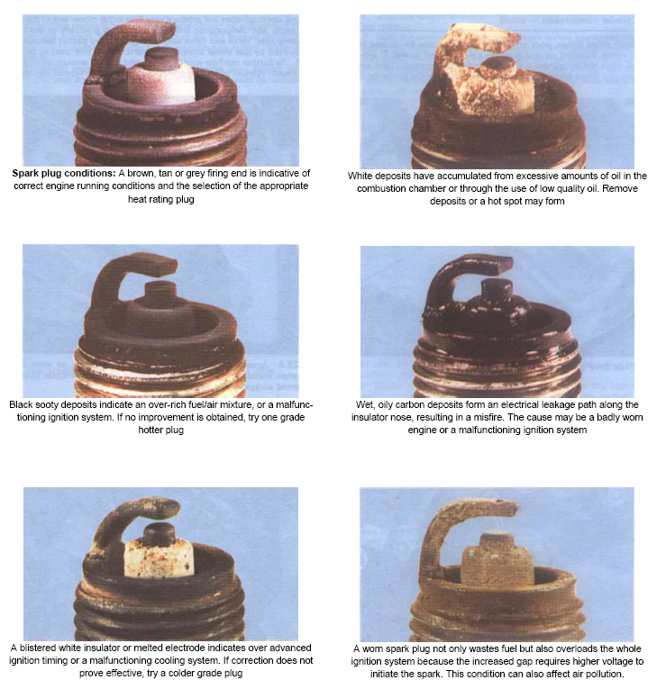
SPARK PLUGS TELL THE TALE
The spark plug itself speaks volumes about how "optimum" the combustion process is. Visually, if the burn is good and combustion heating of the plug is correct (you have the correct plug heat rating) then ..... the plug looks like this. The insulator around the tip of the electrode will appear slightly off-white (light beige). There won't be any heat disfiguring of the electrode and no carbon buildup or soot.
WAIT A MINUTE ....... How important can timing advance be? My lawn mower doesn't have it, or my small magneto outboard, weed-wacker, etc.... Well, your right. And, I don't know exactly. So here's my guess. I won't talk about 2-cycle 'cause that's a different animal. But other small motors... you simply aren't demanding that much out of them (throttle acceleration, load under changing rpm) to notice any major performance loss from no advance. So the motor is set at a worse case timing. Not optimum, but still runs consitantly. At some point the motor and motor load/performance/hp makes timing advance worth it.
Common Problems with a conventional ignition system are:
- Points wear and erode (poor current flow and sloppy timing)
- Points limit power input to coil (limiting coil output)
- Point dwell limits and "point float" or "bounce" limit high power at high RPM
- Mechanical Advance and vacuum advance wears
- Advance cannot be mechanically adjusted for all the variables, especially detonation
- Points get wet and stop working altogether
- Timing belt (chain) wears and/or breaks
Basic Electronic Ignition Transistors and Pickups Sensors
The first improvement of electronic ignition was to replace the mechanical points with a "solid state" semiconductor switch called a transistor (pictured above) This is called a "fast switching transistor" to be exact. The advantage of an ignition transistor is that it can conduct up to near 400-500 volts (more power than needed), is extremely accurate fast (in nanoseconds vs. milliseconds), and can last a long time in the heat / vibration of an engine. The trick of course if how to trigger the transistor switch. The common types of sensor systems that have evolved are: magnetic, "Hall" effect, optical, and (for trivia purposes only) "ECKO". In order of today's usage:
"Hall Effect" Pickups Most Commonly
Used in Modern Autos
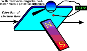
This is the most widely used type of ignition sensor. The Hall effect (named after the American physicist Edwin Herbert Hall, 1855-1938) involves the generation of an "electric potential perpendicular to both an electric current flowing along a conducting material and an external magnetic field applied at right angles to the current upon application of the magnetic field". SAY W-H-A-T ?!??. Practically speaking, a current is passed though a silicon wafer. When a exposed to a magnetic field this disrupts the current flow and distributes more "potential" on one side of the wafer. This can be measured, conditioned, and amplified to trigger the ignition module. Hall Effect sensors are extremely accurate, they produce a "square" wave signal perfect for solid-state applications, and are very durable against heat / vibration. The rotor magnet does not need to be as strong (you may not feel its pull with a heavy screwdriver).
Most Hall effect rotors involve a stationary Hall Switch and stationary magnet. What rotates is an "Interrupter Blade". When the blade passes between the sensor and the magnet it blocks the magnetic pull on the Hall Switch. When a "shutter blade" is open, the magnetic field projects onto the Hall Sensor switching it on. The easy way to identify a Hall system is the fact that it must be externally powered. So, there's going to be that extra wire.
Magnetic Pickups (Most common
in everything other than Auto)

This is very popular and still used for many applications today because its a rugged durable design. In addition the sensor is not powered (like in Hall Effect) so it can be used in self powered magneto ignition applications. A coil sensor is used to detect the "flux" a magnet produces when it passes close by the sensor. This magnetic rotor is called a "Reluctor" (I betch ya didn't know that one). The problem with magnetic is that at higher RPM the sensor has trouble seeing "teeth" close together on the magnetic rotor. This is a bigger problem with many cylinder engines and/or high RPM applications. Also, you may remember magnets tend to loose their strength with vibration and heat. Also, reluctors are stronger magnets (you can definitely feel the pull if you get a screwdriver close) which tends to magnify things around it.
Optical
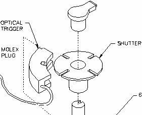 An infrared sensor triggers
when a rotor blade blocks the light path. Although accurate,
the sensor is sensitive to dirt and dust. This is not used much
but is very common in aftermarket ignition kits because its easy
to adapt to almost any application.
An infrared sensor triggers
when a rotor blade blocks the light path. Although accurate,
the sensor is sensitive to dirt and dust. This is not used much
but is very common in aftermarket ignition kits because its easy
to adapt to almost any application.
ECKO
"Eddy Current Killed Oscillator" systems were used by Lucas (yeah, the British "Dark Lord"). It involves a 2 coil sensor that has current flowing. The sensor detects the current disruption cause by a magnet passing by. It is similar to "Hall Effect" in that it is extremely accurate and durable. But for whatever reason is only used mainly in manufacturing automation applications.
For the most part, there are 2 types of ignition systems in use today (or variations of them): Induction ignition (TCI=Transistor Controlled Ignition) or CDI ("Capacitive Discharge Ignition"). Both systems use a sensor (discussed above) to trigger a transistor switch (which has replaced the points). CDI is becoming the standard and you'll see why.
This is called an induction system because the coil is used as a power storage (an "inductor") device for the spark. Remember, the coil is powered up, stores near 30,000 volts, and unleashes it when the coil collapses (power supply cutoff). A feature of induction ignition is the slightly longer spark duration while the coil collapses. This is an advantage when starting and for igniting lean/high compression mixtures at high RPM. These type of systems require coils meant for "induction" ignitions (they have a higher resistance typically than CDI coils). Induction ignitions are simpler in design (cheaper) and used often on less sophisticated motors.
Commercial development of CDI happened around the mid 60's.
Up till then it was regarded as worthless and even dangerous.
Well.. the dangerous part is somewhat right as you will see.
If your really bored here's a 1965 Danish sketch of an early CDI design and the bike it was tested on (a 90cc Kawasaki
motorcycle). Automotive CDI was pioneered mainly by Bosch in
Europe. In 1979 they introduced the "Bosch Motronic".
Today we see a variety of names to include: Ford's TFI (Thick
Film Integrated), GM's HEI (High Energy Ignition), DIS (Distributorless
Ignition System), ECU (electronic control unit), and many others.
CDI ignition is most widely used today on automotive and marine
engines. A CDI module has "capacitor" storage of its
own and sends a short high voltage (about 250+ volts) pulse through
the coil. The coil now acts more like a transformer (instead
of a storage inductor) and multiplies this voltage even higher.
Modern CDI coils step up the voltage about 100:1. So, a typical
250v CDI module output is stepped up to over 25,000v output from
the coil. The CDI output voltage of course can be higher. So
you'll see CDI systems claiming coil output capability over 40,000-60,000
volts!!? As you will see this is not exactly what happens at
the plug but for math purposes it works out. The huge advantage
of CDI is the higher coil output and "hotter" spark.
The spark duration is much shorter (about 10-12 microseconds)
and accurate. This is better at high RPM but can be a problem
for both starting and/or lean mixture/high compression situations.
CDI systems can and do use "low" resistance coils.
With the Kettering Induction ignition design, the coils are powered all the time at 12 volts and are commanded to collapse to spark by the ignition module. Here, the ignition module disconnects the primary winding coil ground. The coil secondary winding collapses to spark at about 30,000 volts. In the CDI design, the coils are not powered. They receive a short high (250 volt) pulse from the ignition module and then amplify that (100:1) to a much larger voltage spike (about 40,000 volts) . Since the potential output of a CDI coil can be over 40,000 volts you have stickers all over your engine bay reminding you that: This can KILL you!!
The advantages of solid state are numerous but the big one is : "no moving" parts. This should translate to control and reliability impossible to achieve in any mechanical system. The term "engine tune-up" is nearly meaningless with respect to modern ignition systems. Outside of replacing plugs and inspecting wiring there is not much else to do. More than a few mechanic shops exploit the public misunderstanding of modern engines. Having said that, the disadvantage of electronic ignition is simply reliability.
A desktop computer circuit board should last a LONG time in theory, and yet you know quite clearly it does not sometimes. Ignitions have suffered the same evolution of making electronics that can stand the test of time. Early ignition systems were particularly prone to "component" breakdown. Anyone who has owned an older British sports cars will understand the term "the dark Lord of Lucas" (Lucas Electronics were notorious for their failure).
Solid state components are particularly sensitive to heat, thermal stress, vibration, moisture, and power surges (basically, everything an engine is about). So, great strides have been made to beef up and improve CDI reliability. These include things like:
- Improved cooling and heat sinks
- Epoxy resin or Epoxy-rubber encasing components so they can't get wet
- Using separate ignition modules for each plug (so a single failure won't kill the whole engine). This concept was first exploited in outboards where each plug has a separate "power pack". Power pack failures were a big problem in the outboard industry for awhile and not funny when you are 60 miles from land in a small sport fisherman with 1 engine.
- Heavier duty components that can withstand the heat, vibration,
and "duty cycles".
Clearly, CDI is being used for most all modern auto / motorcycle
/ marine applications. It is also the choice for most high
rpm race engines. This is simply due to the ability to fine tune
all aspects of the combustion process electronically. Where
simplicity and reliability is a factor, induction systems have
an advantage. That is why you see them most often in aircraft
engines. High revving RPM control is not the emphasis but
rather reliability. The longer spark duration of induction systems
gives a better chance that combustion WILL take place!
Anyone who has ever flown at night over mountainous terrain and
has heard "auto-rough" knows what I'm talking about
here.
Dwell time refers to the time the distributor points are closed.
The dwell angle was the amount of rotation of the crankshaft
that corresponded to the points being closed. This affects the
charge time of the coil. Dwell was important then because at
higher RPM the dwell time (points are closed to charge the coil)
was not enough to fully charge the induction coil. That meant
less voltage spark at higher RPM (...BAD). There was also the
problem of how fast a point could open and close without "floating"
(a problem you have with valves also). There was a real balance
between dwell time at high RPM, how much voltage you needed for
high RPM spark, how much voltage you could actually push thru
a point without burning it up, and then what would happen at
low rpm (long dwell times) when all that voltage was just heating
up the coils.
In newer CDI systems this term is near meaningless for several
reasons. Solid state transistors control the discharge pulses
electronically with near instantaneous timing in the nanoseconds.
So the dwell times can be finely controlled to achieve the best
coil output. Transistors can handle a LARGE amount of voltage/current
(compared to points). And, newer generation coils are extremely
fast with charge "saturation" times around 1milliseond.
Their coil pulse "voltage rise time" to the plug is
VERY fast at around 6 microseconds. So charge / discharge times
are not a huge factor (unless racing). Newer racing ignitions
(like MSD) are NOT producing bigger sparks with long durations
but in fact getting more efficient burn by producing very controlled
multiple short duration sparks to the plug.
Timing curves can be manipulated in great detail to maximize engine horsepower. Replaceable "high performance" chips for many sport cars are routinely offered by aftermarket companies as a byproduct of racing technology. While it seems logical that auto manufacturers already put the "best timing" they had in an engine design, you could argue that they also may detune an engine slightly to address reliability and longevity of an engine. It has always been a balance between performance (Horsepower) and "how long" an engine will last. You can often squeeze a few more HP out of an engine by improving the timing curves.
Induction ignition uses higher resistance coils compared to CDI is ystems that can use lower resistance coils. So....Do Not Use a "racing" -or- low resistance type coil in an "induction" ignition (or TCI) system unless it is specifically designed for that. The low resistance coil will flow more current thru the TCI and produce the legendary "Hot Toaster" effect. Though it will work for awhile, you will eventually burn the TCI module out.
Obviously, it seems harsh on the components to be powering the ignition system when when the engine is NOT running but the key is on. So, both types of ignition designs employ some auto shutdown of the ignition modules. This is usually tied to the pickup sensors. If no RPM is observed then the ignition is shut off (as well as is the high pressure fuel pumps for the fuel injection system). I mention this because in older Induction (TCI) designs when the ignition module shuts off, it collapses the coil. You would occasionally get a single backfire a second or two after trying to start a engine that didn't run.
The Big Myth: Your engine needs a tune up!
If you've understood any of this then the question that should come to mind is: What do they adjust when you take your car in for a "tune-up". The obvious answer: NOT MUCH !! If you own an older electonic ignition (80-late 90's) a shop can:
- Replace the spark Plugs
- Check the plug wires
- Check the wear and replace the distributor rotor (if there is one)
- Check the wear and replace the timing belt (if there is one)
There are no points to replace, no dwell or timing to change.
In the "New Millennium" high-end car & marine engines
have neither a timing belt, distributor, plug wires, etc... You
guessed it., there ARE NO MOVING PARTS and NO
ADJUSTMENTS. It either WORKS -or- IT DOESN'T.
All they can do is change the spark plugs. AND YOU SHOULD.
Now... in fairness, the truth is: a dealer (or very good
shop) WILL plug your high end machine into a $300,000
diagnostic computer which will tell whether all those sensors
(you don't know about) are working correctly to produce max horsepower,
best gas mileage, no knocking, and clean "California"
exhaust so LA people can breath what little is left of their
air and your catalytic converter doesn't have a Chernobyl meltdown.
And... these things could be important.
But generally, if your car is running good (no engine light).... just change your spark plugs occasionally (if you can find them) !?
The common question is: how much power do you need in an ignition system? The more the better right? Well, not exactly. Lately it seems the talk is always centered around high voltage (50,000+) low resistance racing coils, aftermarket ignitions (MSD, Accel), etc... What is really important?
Coil aspects: "Rise time" refers to the time needed for the coil voltage to reach 90% of its peak. Fast rise times are desired as they help prevent and breakdown plug fouling (or "plug tracking"). Plug fouling occurs when the spark is dissipated and runs to "ground" across deposits on the plug's surface instead of across the plug gap. These deposits can be carbon buildup, corrosion, lead salts, water, etc. Rise times for ignition systems are typically 80-120 microseconds for induction systems and 6 microsecond for CDI.
It takes about 10-14,000 volts to initiate the spark across the plug gap. After the initial arc the voltage required to sustain the arc is much less and drops off significantly. So while you may have a manufacturer claimed 60,000 volt racing coil you can't actually get that across the plug. Since the advantage of CDI is the higher coil output, how does that get used. Well, normally it doesn't. The extra power possible in the coil is "Reserve Voltage". As the plugs wear, fouling, plug wires and connections get worse then the required firing voltage may go up 1-5,000 volts. So the "hotter" CDI coil output can help overcome these obstacles and the ignition system will last longer. So, its not that its working better.... but rather lasting longer that makes a hot coil good. The ideal coil output needed for normal applications is about 30,000 volts.
High RPM / High Compression / Racing applications: Newer techniques are being used to increase spark output. Additionally, CDI typically has a very short spark duration near 10-12 microseconds. As discussed you can't push more than about 20,000 volt across the plug without other strange phenomenon happening. If you were to try you would see arcing down the side of the plug, across carbon buildups at the electrode end, out any weak points in the wire insulation, connections, etc... So how do you get a better spark? Newer ignitions (like MSD-5 for example) are outputting a finely controlled multiple spark pattern into the plug. Instead of one big spark a shower of short duration sparks are flooded across the combustion stroke. This makes for a much more efficient burn. Using this technique newer CDI can achieve longer spark duration times (near 250). This is particularly better for starting, lean mixtures (which are hard to ignite), and high compression situations.
Ignition Memory: Most modern auto ignitions keep a profile of engine performance with respect to recent usage. So the type of gas you use, environment you drive in, and the way you drive with effect how the engine anticipates its timing curves and ignition / fuel / emission settings. Another words, if you drive mostly in Florida and then move to the high altitude Rockies.... you've car is going to run rough for awhile till it catches up. Most ignition memories can be "zeroed" out by removing power from the car for a "noticeable" length of time (30 minutes?)
The GOOD NEWS is the ignitions systems are getting very reliable, accurate, and sophisticated. The BAD NEWS is that you can't work on it. I looked under the hood of a new Ford F-150several years back .... and .... "where's the spark plugs?" For that matter, where are the spark plug ....wires..... and ..... coil !??! Yeah, do I feel dumb.
|
|
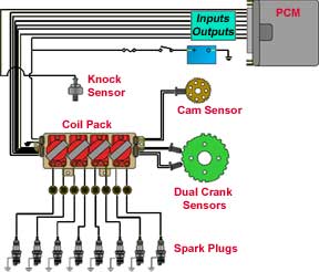
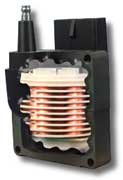
New generation auto ignitions are designed for more accuracy, better efficiency and reliability. This includes" crank angle" sensors to improve timing and fuel injection accuracy (example, mounting the Hall sensor and magnets on the flywheel). Newer coils will be wound around an "E" shaped pole (not "center wound"). They will look like a square module and not the round cylinder you've seen all these years.
"DIRECT IGNITION": (first seen on Saab's and GM's ). In this setup each spark-plug has its own coil -or- a single coil will supply opposing cylinders. The advantage here is no more rotor. DIS systems are usually inductive ignitions and employ the "wasted spark" strategy. This refers to a coil that supplies the spark on every revolution so the cylinder will get one during compression and also during the exhaust stroke. The wasted spark design cuts the coil charge time in half so is not often used on extreme high rpm race engines.
"COIL ON PLUG": This design is becoming more prevalent. You'll see separate coils mounted directly atop each spark plug. This improves spark power (no plug wires), accuracy, reduces RFI (radio frequency interference) problems, and most importantly eliminates the distributor (the last moving mechanical device to wear in ignition systems). The advantage here is total control, no moving parts, and extreme high rpm capability. This is the design used on most Indy and F1 engines which are generating nearly 15,000-16,000 rpms.
Timing and spark duration times can adjusted across the RPM range. Additionally, timing advance will be calculated for a variety of inputs including increasing RPM vs. decreasing RPM (braking, coasting, or accelerating), throttle position, temperature, altitude, etc. Even "engine knock" (detonation) will be eliminated by timing adjustments (using "listening" sensors like piezoelectric crystals bolted to the engine )
(For normal operations)
Simple , and in order of importance: Plugs, Plug-wires, CDI, Coil.
The biggest enemy against ignition is RFI and insulation leakage. Basically, you want the best insulated (thicker, 12mm?) and well made plug wires you can get. Remember this simple gradeschool phrase: "... electricity takes the path of least resistance". In the case of your engine this will be arc tracking across the plug and/or out the plug wires due to insulation breakdown. Upgrade your CDI module (example: performance timing curves, high output, etc...) if you want to spend a little more for higher performance. Although a good coil is always a plus, we've discussed how meaningless SOME manufacturers high output claims can be in practicality.
In short, spend your money on a good well insulated system. As long as the coil and CDI can meet the rpm demand's of the engine you are on top of the game.
There are 3 basic types of conductors used in automotive applications: Carbon string, solid and spiral wound. Spiral wound is becoming the more popular so there's probably a good reason. I recommend getting on some really good "wire" sites and scoping out the differences. MAGNECOR or NGK would be a good place to start.
This is a bar conversation if ever there was one.....right up there with synthetic vs normal oil. But I believe most standard plugs these days are more than adequate. NGK, Bosche, Champion..... are all good. Platinum plugs are the way to go because they simply last longer. A good plug should last about a years worth of normal use (20-30,000 miles). If using the engine in more extreme load/rpm ranges you should consider a plug with a different "heat" rating. As an example, an engine operated in constant high rpm/power/load situations might benefit from a colder (than "stock") plug rating. Since the engine is running hotter, a "cold" plug would run cooler thereby preventing pre-ignition (helping the plug and engine last longer).
.
http://www.442.com/oldsfaq/ofign.htm
From dave andrews motorcycle repair page
http://members.aol.com/DVAndrews/timing.htm
dan motorcycle garage
http://www.dansmc.com/IGNITIONTIMING.html
from simple digital systems fm-4
http://www.sdsefi.com/techcomb.htm
runtronic spark ignition
http://www.barbwireweb.com/EELC/jep/runintro12.htm
SEARCHES:
Try to use search word that would only be used in discussion of ignition systems. Examples:
CDI ignitions
capacitive discharge ignition
induction ignition
kettering design
votage rise time ignition
dwell ignition
centrifugal advance ignition
vacuum advance ignition
detonation
preignition
hall effect ignition
Just throwing some names out here IN NO ORDER.
| MSD | Accell | Intelligent Ign System (Iss) | Lucas Rita |
| Dynatek | Boyer |
M&W Ignitions www.mwignitions.com/ |